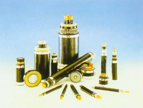
- Cross-linked polyethylene (XLPE) insulating power cable
- Aerial insulating cables with rated voltages of 10KV
- 0.6/lkv PVC insulating PVC sheathed (fire-proof)power cable
- 0.6/lkv PVC insulating, steel belt sheathed, PVC covered (fire-proof) power cable
- 0.6/lkv Cross-linred PVC insulating,PVC sheathed fire-proof power cable
- 0.6/lkv Cross-linred Polyethylene insulating,steel strip sheathed,PVC covered fire-retardant power cable
- PVC insulating power cables for rated voltages up to 0.6/1KV
- Local communication cable
- Digital communication-used category V & VI cables
- Shielded cable
- Strip branch cable
- Rubber-sheathed and mine-used flexible cable
- Physical high-foaming polyethylene insulating cable and Series solid polyethyene insulating radio frequency coaxial cable
- Several pairs shielded signal cable for electronic computers
- Prevent fire the electric cable
- Wire & cable-used PVC insulation plastic and plastic for protective layer
Jiangsu Yuanfang Cable Factory Co.,Ltd.
Address: Guanfeng Road ,Guanlin Town, Yixing City, Jiangsu Province
Phone: 0510-87290353、87297889
Fax: 0510-87296001
E-mail: yuanfang@Yuanfang-cn.com
yuanfangdianlan@163.com
Address: Guanfeng Road ,Guanlin Town, Yixing City, Jiangsu Province
Phone: 0510-87290353、87297889
Fax: 0510-87296001
E-mail: yuanfang@Yuanfang-cn.com
yuanfangdianlan@163.com
Cross-linked polyethylene (XLPE) insulating power cable
Cross-linked polyethylene (XLPE) insulating power cable
35KV and down Cross-linked polyethylene(xlpe)insulating power cable
| Your present position:35KV and down Cross-linked polyethylene(xlpe)insulating power cable | |
|
 |
which is higher than that of paper, PVC or PE insulated power cable. The cable has the advantage of simplicity in construction, lightness in weight, convenience in application besides its excellent electrical, thermal, mechanical and anti-chemical corrosion properties. It can also be laid with no limitation of level difference along the route.
Standard: The product is manufactured according to the standard of GB12706 or IEC, BS, DIN and ICEA upon request. Applications: The product is suitable for use in power transmission and distribution lines with rated power frequency voltage 3.6/6kV-26/35kV. Operating characteristics: 1、Rated power-frequency voltage U0/U: 3.6/6kV-26/35kV. 2、Max. Permissible continuous operating temperature of conductor: 90℃. 3、Max. short-circurt temperature of conductor shall not exceed 250℃. (5s maximum duration) . 4、The ambient temperature under installation should not below 0℃. 5、The bending radius of a single-core cable should not less than 20 times of the cable diameter. The bending radius of a three-core cable should not less than 15 times of the cable diameter. Voltage designation: 1、The rated voltage of the cable for a given application shall be suitable for the operating conditions in the system in which the cable is used, and is expressed in the form of U0/U(Um)kV. Where: U0--The rated power-frequency voltage between conductor and earth or metallic screen, for which the cable designed; U --The rated power-frequency voltage between conductors, for which the cable designed; Um--The maximum value of the "highest system voltage" for which the equipment may be used. 2、The values ofUo recommened for cables to be used in three-phase systems are listed below. 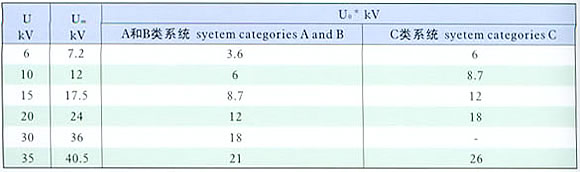 System category A-- This category comprises those systems in which any phase conductor that comes in contact with earth or an earth conductor, is disconnected from the system with in I min. System category B-- This category comprises those system which, under fault conditions, are operated for a short time with one phase earthed. This period should not exceed I h. For a longer period, not exceeding 8 h on any occasion, can be tolerated. The total duration of earth faults in any year should not exceed 125 h. System category C-- This category comprises all syatems which do not fall into categories A and B. |
|